| < Prev | Contents | Next > |
2.5. Pressures
 |
2.5.3. Well Control Kill Sheet |
Well control kill sheet was designed to assist the mud engineer in a well kick and kill situation. The objective of the various kill methods is to circulate out any invading fluid and circulate a satisfactory weight of kill mud into the well without allowing further fluid into the hole. Ideally this should be done with the minimum of damage to the well.
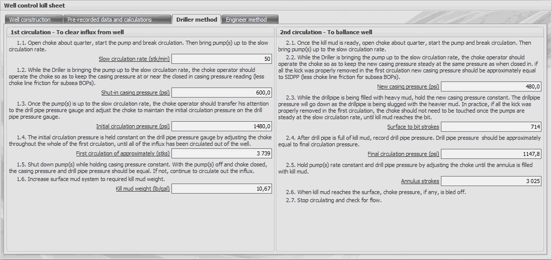
The program contains the calculations for the two "constant bottom-hole pressure" kill methods in common use today which are:- Driller's method;
- Wait & Weight method (also known as the "Engineer's Method").
In the Driller’s method, the kill is split into two circulations. During the first, the kick fluid is circulated without changing the mud weight; once the kick is out, the mud is weighted up and pumped around the well on the second circulation. The Engineer’s method achieves both of these operations simultaneously. Kill mud is prepared before starting the kill, and the kick fluid is circulated out while this mud is circulated into the well. The Engineer's method is the most popular and recommended for use in most instances. It produces lower well pressures than Driller's method, with an evident benefit to safety.
Well control kill sheet task contains four sections: Well Construction, Pre-Recorded Data & Calculations, Driller Method and Engineer Method.
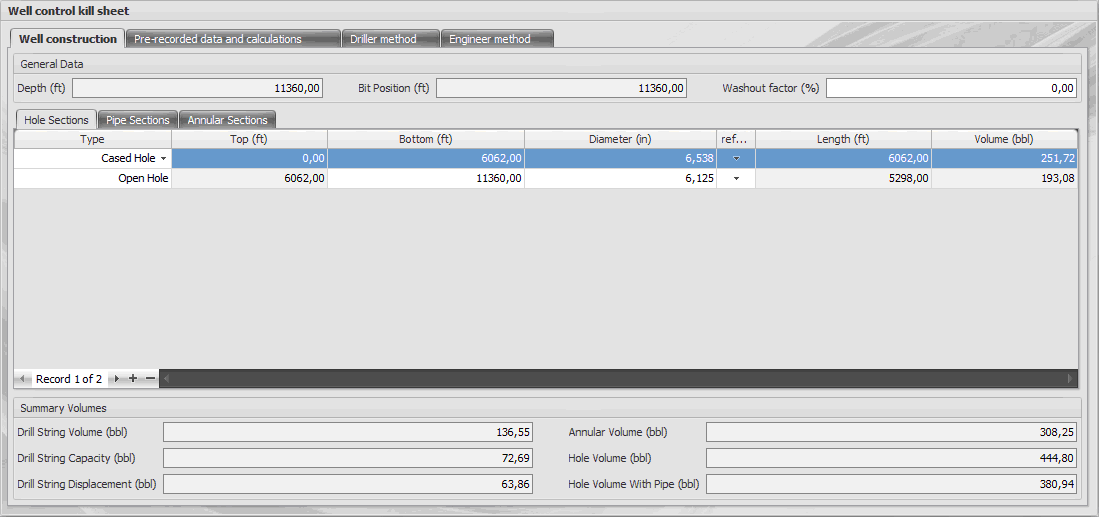
The first tab Well Construction contains a description of well construction and construction of drilling tools in the well. On the basis of the well construction calculated annular and pipes volumes, well depth and the depth of the bit. Description of the input well construction, see the section Well volume.
The main application of Pre-Recorded Data & Ńalculations section is input of actual parameters are required to describe of well kick and calculate required data for remove of influx from the well.
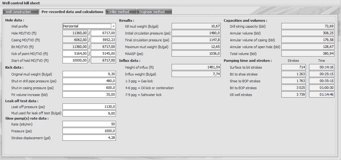
The calculations used three types of well profile: vertical, highly deviated and horizontal. Depending on the well profile program provides the input necessary data and calculates the pump pressure schedule, used in the Engineer method. Well profile entered in the same name field "Well profile".

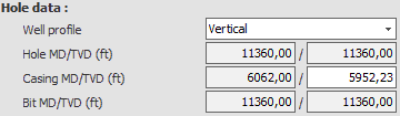
When choosing a Vertical well profile believed that the measured depth of the hole (Hole MD) and the true vertical depth (Hole TVD) are approximately equal. Accordingly, the bit depth (Bit MD) and the true vertical depth of the bit (Bit TVD) are also equal.
The measured depth of casing shoe is calculated on the basis of well design. For enter available only field "Casing TVD" - true vertical depth of casing shoe. Entering this parameter due to the need to specify a more accurate value used in the calculation Maximum mud weight and MAASP (maximum allowable annulus surface pressure).
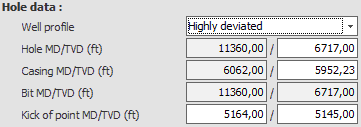
If the well profile is Highly deviated, you must enter a true vertical depth of the hole (Hole TVD) and specify the kick of point. For a kick of point you must enter the measured depth of point (Kick of point MD) and the true vertical depth (Kick of point TVD).
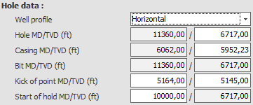
For a Horizontal well, you must enter an additional point "Start of hold" - the point at which the wellbore is held horizontal. For this point specify only measured depth. In this case, true vertical depth for this point is equal Hole TVD.
| Input Values | ||
 |
Original mud weight | Density of the mud in the well |
|
Shut-in drill pipe pressure | The pressure that is read on the drill pipe when a well is shut-in |
|
Shut-in casing pressure | The pressure that is read on the casing side of the well when the well is initially shut-in (less choke line friction for subsea BOPs) |
|
Pit volume increase | Any invasion of formation fluid must result in the expulsion of mud from the well, and this shows up as an increase in surface volume |
Parameters of Leak off test block are used to enter data on the test. These data are necessary to calculate Maximum mud weight and MAASP (see Results block).
The Slow pump(s) rate data block is used for input of a predetermined pump(s) rate and pressure which can be used to kill a well which has experienced a kick:| Input Values | ||
|
Rate | Slow circulating rate |
|
Pressure | Slow circulating pressure |
|
Strokes displacement | Used to calculate the time and quantity of pump strokes needed to fill the well with a kill mud (see Pumping time and strokes block) |
The Results block displays the calculated parameters necessary for killing the well:
| Results | ||
 |
Kill mud weight | The mud with this density creates a hydrostatic pressure equal to or greater than the pressure of the formations exposed to the well bore |
|
Initial circulating pressure | Drill pipe pressure required to circulate initially at the selected slow circulating rate while holding casing pressure at the shut-in value, numerically equal to slow circulating pressure, plus shut-in drill pipe pressure |
|
Final circulating pressure | Drill pipe pressure required to circulate at the selected slow circulation rate adjusted for increase in kill mud weight over the original mud weight. Used from the time kill drilling fluid reaches the bottom of the drill string until kill operations are completed |
|
Maximum mud weight | Used to calculate MAASP |
|
MAASP | Maximum Allowable Annular Surface Pressure is defined as the surface pressure which, when added to the hydrostatic pressure of the existing mud column, would result in formation breakdown at the weakest point in the well. This value is normally based on leak-off test data, with the assumption the area below the last casing shoe is the weakest point in the well |
The Influx data block contains information about height and estimated type of influx.
Blocks Capacities and volumes and Pumping time and strokes contain information on the volume of structural elements well, as well as of the time and quantities of pump strokes needed to fill the hole with mud as a whole and for various construction elements in separately. When pre-recorded data is entered and the required parameters are calculated, the mud engineer can use one of two instructions given by the program.
The tab Driller Method describes the sequence of actions and conditions necessary for killing the well by this method.
The tab Engineer Method contains instructions for killing the well by the engineer method.
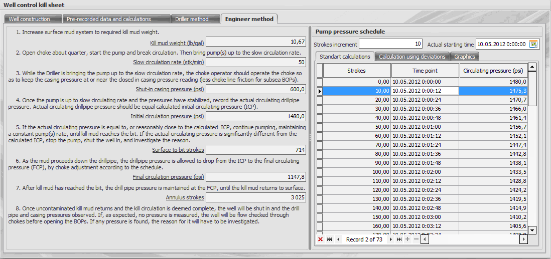
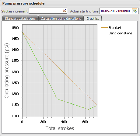
To calculate Pump pressure schedule mud engineer must enter the increment of pump strokes and, if necessary, the actual starting time killing the well.
The Pump pressure schedule is calculated in two ways. The tab Standard killsheet shows the calculation of the pressure a standard way. It can be used for vertical wells. For Horizontal and Highly deviated wells is necessary to use pressure calculations presented in tab Calculation using deviations. In calculating the pressure using the geometry of drill string and points of curvature of the wellbore (Kick of point and Start of hold).
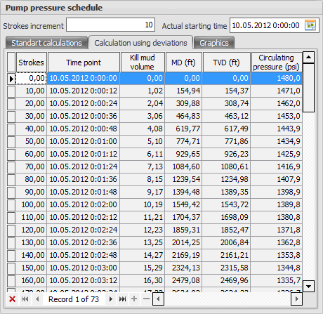
The pumping pressure graph will contain a record pressure at intervals equal to the entered increment, starting from the beginning of killing the well and before reaching kill mud of the bit. To view a graphical representation of the Pump pressure schedule used tab Graphics.